It Starts with an SCR
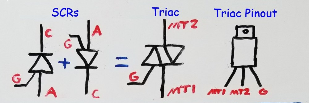
You can think of an SCR (silicon controlled rectifier) as a diode with a control line. Referring to the image below, the SCR works like a diode in that it will only allow current to flow in one direction – that is to say, current will not flow until the anode (A) is positive with respect to the cathode (C). For current to flow through the SCR though, you need to satisfy another condition. You must bias the gate so that it is positive with respect to the Cathode (but only for enough time to get current flowing). Once current starts flowing through an SCR, it acts just a diode. So you can remove the gate “trigger” voltage, and the SCR will keep conducting.
*CLICK HERE TO DONATE*
*CLICK HERE FOR THE FREE ELECTRICITY MICRO-COURSE FOR APPLIANCE TECHNICIANS*
How do you stop the SCR from conducting? You remove the voltage source. Once you then re-apply that voltage source, the SCR will not conduct until the gate is again “triggered” with a voltage that is higher than the cathode.
So What is a Triac?
Electrically, a Triac is the equivalent of two (respectively inverted) SCR’s in parallel with their gates tied together. This effectively makes it an AC device. This is because when you apply a sine-wave to the Triac, you have an opportunity for current flow in either direction. This current can only flow however, when the gate triggers the internal SCR that is forward biased (depending on what part of the waveform the trigger occurs).
How to use a Triac
Remember that you can only get a Triac to conduct when you apply a positive bias to the gate with respect to the cathode of the internal SCR that is forward biased. Which SCR is forward biased depends on what half-cycle of the waveform is in. Referring to the images below, there are four cases considered.
Case 1: The AC Relay
You can create the equivalent of an AC relay by using a Triac. Referring to “Case 1” on the below image, the load is connected between “hot” and MT2 of the Triac. MT1 is connected to “neutral”. Using a switch, you apply a bias to the gate through a current limiting resistor. When you close the switch, the gate triggers the internal SCR that is forward biased, depending on which part of the waveform you are in. So if you are in the positive half-cycle, SCR2 is triggered, and if in the negative half-cycle, SCR1 is triggered. Note that the sine wave depicted in Case 1 is “full-on” as denoted by the red filled-in area. When you open the switch, the load is effectively no longer energized. Thus this configuration is the equivalent of a relay.
What is important to note is that if you open the switch after you have triggered the gate, the Triac will continue to conduct until it reaches the “zero-crossing” point. Although you wouldn’t perceive this in practicality, this fact is highly relevant when considering microcontroller (uC) based Triac control – which you will find in Case 3 and 4 further below.

Case 2: The Analog Dimmer
As shown in the image above, you can create a dimmer if you make a few changes to the circuit – by getting rid of the switch and replacing the resistor with a potentiometer. Then connect a capacitor from neutral to the potentiometer. This RC circuit creates a time delay in triggering the Triac. Add a device called a Diac, which only starts conducting when the voltage across it reaches about 30 volts. Once it start conducting, it continues do to do so until you cut off the voltage or when the sine wave “zero-crosses”. In this configuration, you control what specific part of the sine wave in which the Triac starts conducting as depicted in the sine wave. The trigger point is shown as “T” on the sine wave, and the conduction time is shown as the red filled-in area within the waveform. You can see that the conduction starts half-way through the positive half-cycle. This reduces the amount of “power” delivered to the load, which results in a dimming of the light bulb. Note that this circuit only works well with resistive loads such as an incandescent light bulb.
Again, once you trigger the Triac in whatever part of the half cycle you’re in, it will continue to conduct until “zero-crossing” has occurred. At this point, no current flows through it, and it ceases to conduct until re-triggered (much like an SCR, but in a bi-directional manner).
Case 3: The Digital On-Off Switch
You can use a digital (as opposed to an analog or manual) means to trigger a Triac. A microcontroller (uC) is commonly utilized for this (like for a microwave oven hood light). This case is very similar to Case 1 except an opt-isolator is used to electrically separate the microcontroller from the Triac circuit. This is done because you cannot directly control a 120V AC mains circuit with a 5V DC device. The opto-isolator used in this circuit is just a mini photo-Triac that is triggered by the light of an LED. The LED inside the opto-isolator is turned on and off by the microcontroller (uC) , which it can easily and safely do. So when the microcontroller (uC) output is high (5V), the opto-isolator LED turns on and the Triac gate is triggered. Note that just like in Case 1, this circuit acts as an AC relay and has a fully filled-in conduction waveform as shown in the Case 3 image.
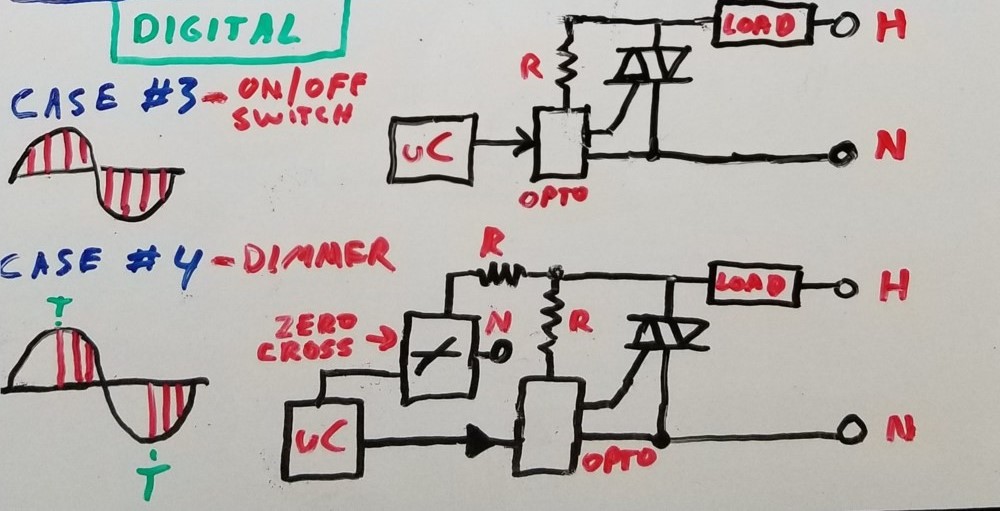
Case 4: The Digital Triac Dimmer Circuit
If you extend the circuit in Case 3, you can use a microcontroller (uC) to dim the incandescent load. This is quite commonly used in appliances, such as over-the-range microwaves to control the surface light intensity. You add an extra opto-isolator that allows the microcontroller (uC) to monitor the sine wave. The LED inside this opto-isolator stays on until you reach “zero-crossing”. This again, is when the sinewave crosses the zero point on the axis and changes polarity. The output voltage of the opto-isolator then goes to zero volts. When the microcontroller (uC) senses this zero-crossing, it will start a timer.
Refer to the sine wave diagram for Case 4 of the image above. Let’s say that you want to dim the load to around 50%, for example. Thus you want to turn the Triac on at point “T”, which is when you’ll want to trigger its gate. The time it takes for a 60 cycle sine wave to reach point “T”, or 1/4 of a cycle is 4.16 mS. So in the microcontroller (uC), once you have started the timer, you’ll want to count to 4.16 mS or 4166 uS. Note that a microcontroller has no problem doing this. This is one of the core abilities of a microcontroller! Once you reach 4.16mS, you send a pulse to the Triac-control opto-isolator, and the Triac conducts – energizing the load. Then, when the sine wave reaches the zero-cross point, the Triac turns off. At this point, the microcontroller (uC) has again detected that zero-cross point and is now waiting to reach time “T” on the opposite half-cycle to re-trigger the Triac. This goes on indefinitely until the microcontroller (uC) is told to do otherwise.
Case 5: The Triac Controlled Motor Circuit
Triac-based on-off induction motor control, which is not depicted in the image, that is commonly found in dishwashers and other appliances is very similar to Case 3. Some additional (snubbing) circuitry is added to make sure the Triac is able to turn off. This is because the phase difference between the gate control voltage and the current passing through the Triac, that is caused by the inductive load, can cause the Triac to continue conducting even after “zero-crossing”.
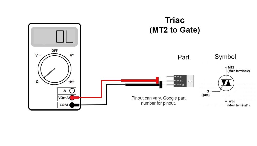
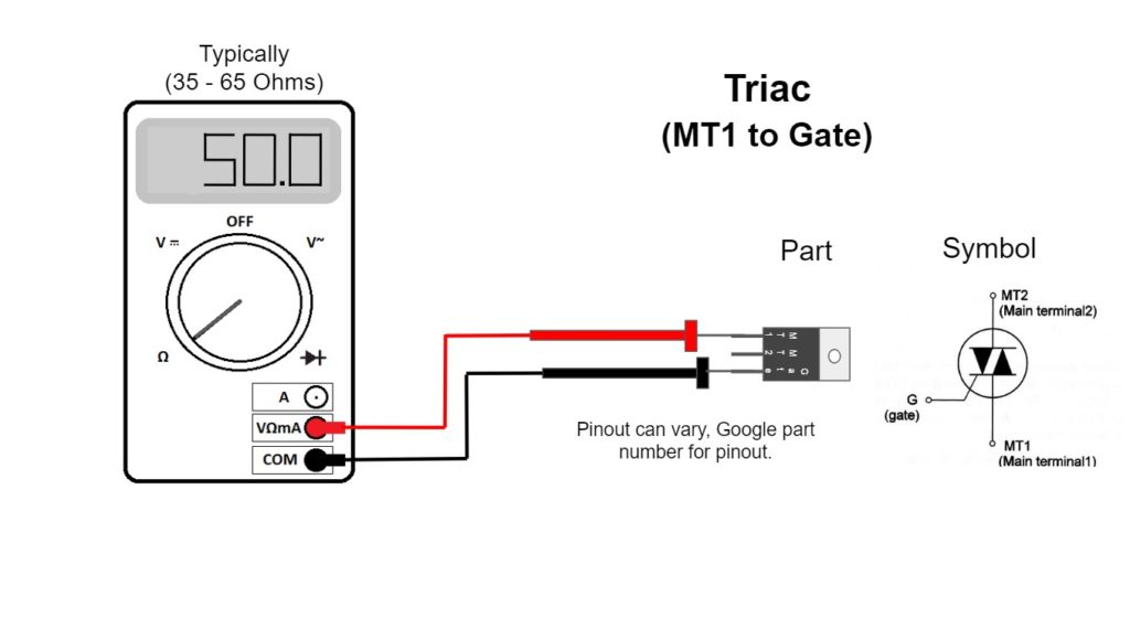
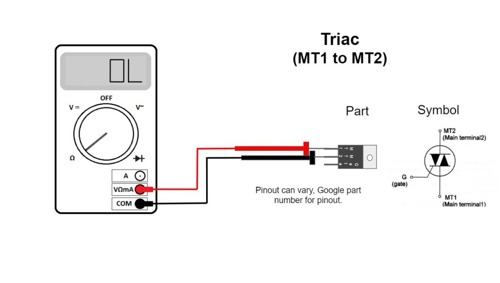
How to Test Triacs
Like most semi-conductors, Triacs often “short out” when they fail. This results in dimmer circuits that conduct full-time. A common symptom on microwave ovens is that the surface light will not shut off. This is because the light that should be off or dimmed is fully energized by the shorted Triac. Below is a quick guide for how to test the most commonly found TO-220 case style Triacs used for light dimming in consumer electronics. Please see my video for how to repair a Whirlpool microwave with a shorted Triac HERE.
Conclusion
Triacs are used as drivers for controlling how much power is delivered to an AC load. Triacs can be controlled in an analog (manual) or digital (such as with a microcontroller) fashion. In this article, you learned about four typical configurations.
- In Case 1, the AC relay, a switch is used to “turn-on” the Triac and cause it to conduct full-time. You likely won’t often see this as an actual relay is simpler to use.
- In Case 2, the manual dimmer, the Triac conducts starting at time “T”, based on a potentiometer, an RC timer, and a Diac. You’ve most certainly seen this used to dim incandescent lights in the home.
- In Case 3, the digital on-off switch, a microcontroller is typically used to trigger the Triac into full-time conduction using an opto-isolator to protect it from the AC mains circuit.
- In Case 4, an extension of Case 3, the microcontroller is used to trigger part-time conduction of the Triac by detecting the zero-crossing point of the sine wave, and waiting until time “T” to apply bias to the gate via an opto-isolator.
- In Case 5, the Triac is configured as a switch for a motor circuit. It is set up much like Case 3, but with some additional circuitry to deal with the inductive delays of the waveform caused by the motor.
Don’t forget:
“Diverting 10 min/day of social media time towards learning something new, is 5 hours of newfound monthly knowledge.” – SM
To DONATE to the Tech Circuit – CLICK HERE
Alphabetical Links to all Tech Circuit Articles and Blogs – CLICK HERE
Links to all Tech Circuit Cheat Sheets/Field References for Appliance/HVAC Techs – CLICK HERE
For additional electrical and electronics learning material for field techs, visit our homepage at http://www.TechCircuit.org or our Facebook group at https://www.facebook.com/groups/746823709133603.
We are a participant in the Amazon Services LLC Associates Program, an affiliate advertising program designed to provide a means for us to earn fees by linking to Amazon.com and affiliated sites.