What’s A TRIAC?
A TRIAC (Triode for Alternating Current) is a three terminal electronic component that conducts current in either direction when triggered.
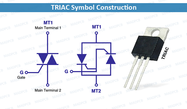
TRIAC Symbol Construction
TRIACs are a subset of thyristors (analogous to a relay in that a small voltage and current can control a much larger voltage and current) and are related to silicon-controlled rectifiers (SCRs). TRIACs differ from SCRs in that they allow current flow in both directions, whereas an SCR can only conduct current in a single direction. Most TRIACs can be triggered by applying either a positive or negative voltage to the gate (an SCR requires a positive voltage). Once triggered, SCRs and TRIACs continue to conduct, even if the gate current ceases, until the main current drops below a certain level called the holding current.
Gate turn-off thyristors (GTOs) are similar to TRIACs but provide more control by turning off when the gate signal ceases.
The bidirectionality of TRIACs makes them convenient switches for alternating-current (AC). In addition, applying a trigger at a controlled phase angle of the AC in the main circuit allows control of the average current flowing into a load (phase control). This is commonly used for controlling the speed of a universal motor, dimming lamps, and controlling electric heaters. TRIACs are Bipolar devices.
Operation
To understand how TRIACs work, consider the triggering in each of the four quadrants. There are four quadrants, and depend on the gate and MT2 voltages with respect to MT1. Main Terminal 1 (MT1) and Main Terminal (MT2) are also referred to as Anode 1 (A1) and Anode 2 (A2) respectively.
The relative sensitivity depends on the physical structure of a particular triac, but as a rule, quadrant I is the most sensitive (least gate current required), and quadrant 4 is the least sensitive (most gate current required).
In quadrants 1 and 2, MT2 is positive, and current flows from MT2 to MT1 through P, N, P and N layers. The N region attached to MT2 does not participate significantly. In quadrants 3 and 4, MT2 is negative, and current flows from MT1 to MT2, also through P, N, P and N layers. The N region attached to MT2 is active, but the N region attached to MT1 only participates in the initial triggering, not the bulk current flow.
In most applications, the gate current comes from MT2, so quadrants 1 and 3 are the only operating modes (both gate and MT2 positive or negative against MT1). Other applications with single polarity triggering from an IC or digital drive circuit operate in quadrants 2 and 3, than MT1 is usually connected to positive voltage (e.g. +5V) and gate is pulled down to 0V (ground).